Date: Mon Nov 15 01:23:58 1999
Posted By: Abtin Spantman, , Electrical Engineering, L. S. Research, Inc.
Area of science: Engineering
ID: 941763257.Eg
Message:
Hi Leo:

In concept, we need to build a 'Low-Pass filter'.  This filter allows the
low frequency audio tones to get through, but stops the higher frequencies
to get through.
There are many ways to build filters. The general catagorization may fall
into two catagories of 'passive filters' and 'active filters'. A simple
capacitor placed between the line and ground would be an example of a
passive filter.  It lets high frequencies pass through it to ground,
effectively killing the high frequencies, and letting only the low
frequency or DC components to remain on the line.  I chose an active filter
design as it does the above, but much better.
I made some assumptions as follows.
1) I assumed the audio tone will be from an 'audio out' source, such
as a tape recorder output, which is somewhere around 1Vpp.
2) I assumed that such things as phase and amplitude distortion are really
not an issue here.
3) I assumed that the light may be larger than a  flashlight type bulb.
4) I assumed that this is just to experiment with, to have fun, at a party
perhaps lighting up on deep base tones. Furthermore, that it will not be
used in any real application.
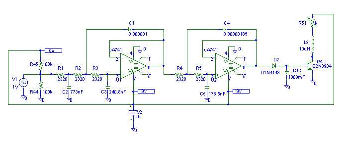
Having said all that, here is the circuit with ideal values calculated:

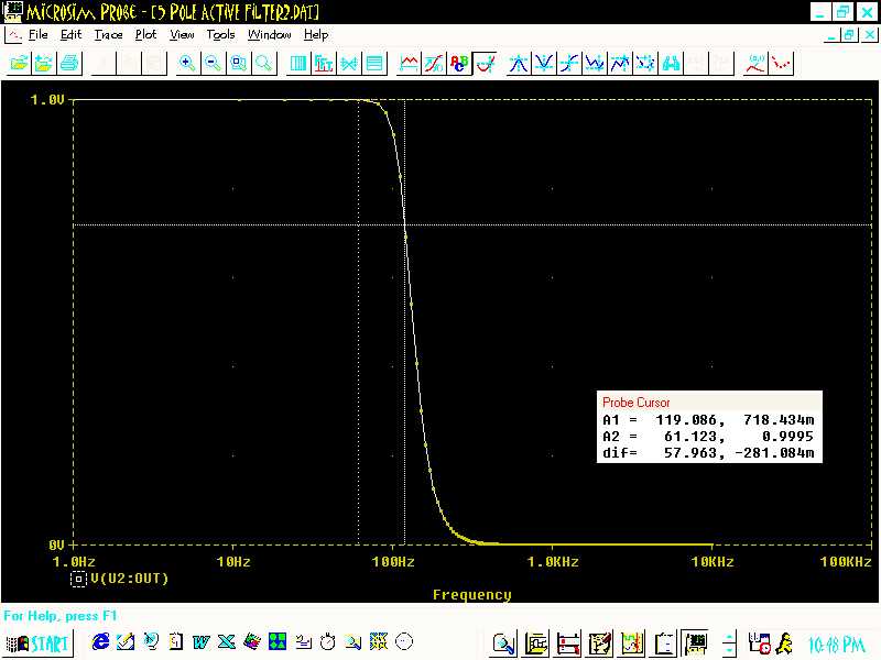
The circuit pictured here had the following response when I simulated it
using PSPICE:

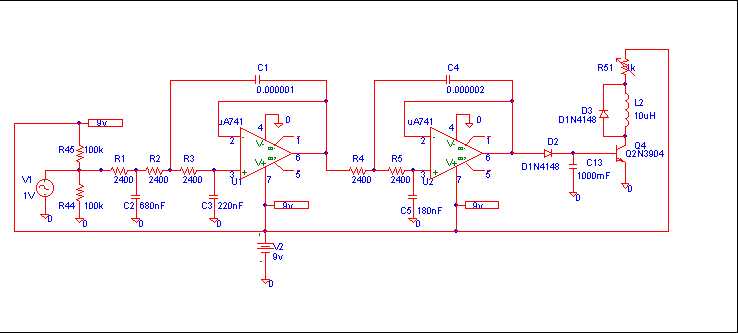
But here is the catch - in real life, we can't get values accurate enough
with decimal points.  Heck, sometimes we are lucky if we can get close at
all.  So I went to the parts room, and I picked out the closest values that
are commercially available, and proceeded to build the circuit shown below:

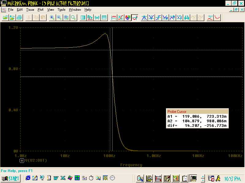
The simulation with the actual values matched up with what I actually
observed in the lab. My lab prototype stopped at about 144Hz. Not knowing
what you intend to use this for, I would venture to guess that it will
probably do just fine for your application.  If, however, you need more
accuracy, try to get as close to the ideal values as you can.
Here is the response you will see if you use the commercially available
values:

I added a transistor to drive a relay (labeled L2- ignore the 10uH) in the
schematic. The relay can be used to drive a light of your choice. The relay
I used was a
generic 5volt relay (Radio Shack). The potentiometer should provide for
some trim-ability on when the relay kicks on and off.  The supply voltage
can vary, somewhat, between 5-12 volts. Just make sure the op-amps have a
high enough voltage rating. Yes, you may substitute other op-amps if you
choose. I used a National Semiconductor LM324, which has four amps on it,
only two of which were needed for the filter.

Watch out to not over drive the input. Don't connect the speaker output to
this circuit. More protection circuitry is needed if the circuit is being
driven off of a speaker port. To give you that protection circuit, I would
need to know exactly what this circuit is being attached to.

Good luck, and let me know how this turns out.

Abtin Spantman
ASPANTMAN@EXECPC.COM
Current Queue |
Current Queue for Engineering |
Engineering archives
Try the links in the MadSci Library for more information on Engineering.
MadSci Home | Information |
Search |
Random Knowledge Generator |
MadSci Archives |
Mad Library | MAD Labs |
MAD FAQs |
Ask a ? |
Join Us! |
Help Support MadSci
MadSci Network,
webadmin@www.madsci.org
© 1995-1999. All rights reserved.
 The circuit pictured here had the following response when I simulated it
using PSPICE:
 But here is the catch - in real life, we can't get values accurate enough
with decimal points. Heck, sometimes we are lucky if we can get close at
all. So I went to the parts room, and I picked out the closest values that
are commercially available, and proceeded to build the circuit shown below:
 The simulation with the actual values matched up with what I actually
observed in the lab. My lab prototype stopped at about 144Hz. Not knowing
what you intend to use this for, I would venture to guess that it will
probably do just fine for your application. If, however, you need more
accuracy, try to get as close to the ideal values as you can.
Here is the response you will see if you use the commercially available
values:
 I added a transistor to drive a relay (labeled L2- ignore the 10uH) in the
schematic. The relay can be used to drive a light of your choice. The relay
I used was a
generic 5volt relay (Radio Shack). The potentiometer should provide for
some trim-ability on when the relay kicks on and off. The supply voltage
can vary, somewhat, between 5-12 volts. Just make sure the op-amps have a
high enough voltage rating. Yes, you may substitute other op-amps if you
choose. I used a National Semiconductor LM324, which has four amps on it,
only two of which were needed for the filter.
Watch out to not over drive the input. Don't connect the speaker output to
this circuit. More protection circuitry is needed if the circuit is being
driven off of a speaker port. To give you that protection circuit, I would
need to know exactly what this circuit is being attached to.
Good luck, and let me know how this turns out.
Abtin Spantman
ASPANTMAN@EXECPC.COM