| MadSci Network: Physics |
Hi Matt,
The dimple pattern on a golf ball is well understood to improve the flight of a golf ball. The problem is that the ultimate physics has many parameters that effect the final answer. Problems complicated by many parameters are solved by numerical simulations or computations. There are many fluid mechanic software packages and I once upon a time started working a simple fluid mechanics/2D electrostatics solver. But I suspect nothing available to the general or student public would be able to handle the complexity of a real golf ball. Some of the parameters involved are: spin rate, dimple depth, number of dimples, speed of the ball in air, density of air. The full list is enormous.
In addition, because the problem has so many parameters there really is no way to come up with all the possible combinations. Any answer is usually an incomplete approximation. But it is possible to show that one pattern might be better than another based on computer calculations. If the computer calculations at least qualitatively agree with the real life experiment (wind tunnel or drive range) then one could say the calculation method is probably a good approximation to reality.
Let me go into the aerodynamics of a spinning sphere in flight. This is what the dimple pattern is trying to improve. This may help give you a feel for what is involved in solving what the dimples on a golf ball do to the flight.
The aerodynamics of golf balls has been studied empirically for more than a century. In 1848 gutta-percha balls were manufactured. Gutta-percha is the dried gum of the Malaysian sapodilla tree. At first these balls were made with smooth surfaces until it was noticed that as the ball was played and its surface roughened the ball would fly farther and straighter.
The first person to seriously consider the aerodynamics of a golf ball was British scientist P. G. Tait in 1887. Tait was a Professor of Natural Philosophy (physics in those days) at Edinburgh University in Scotland and an avid golfer. Before Tait's experiments, the teaching was "all spin is detrimental." This idea probably persisted from the unpredicatable Magnus Effect observed on the flight of cannon balls. The cannon ball would spin in an uncontrolled way out of the cannon and could deflect wildly to one side or up or down.
Here is an excerpt from http://www.b-bop.com/mak/m agnus.html
Newton in 1672(Did this guy have something to say about everything?)
noted how a tennis ball's flight was affected by spin. In
1742, Robins showed that a transverse aerodynamic force could be
detected on a rotating sphere. (Hence it is also referred to
sometimes as the "Robin's Effect"). The first explanation of the
lateral deflection of a spinning ball is credited by Lord Rayleigh to
Magnus, from which the phenomenon derives its name, the "Magnus
Effect".
Rayleigh also gave a simple analysis for a "frictionless
fluid," which showed that the side force was proportional to the free
stream velocity and the rotational speed. This was all before the
introduction of the boundary-layer concept by Prandtl in 1904.
The commonly accepted explanation is that a spinning object creates
a sort of whirlpool of rotating air about itself. On the side
where the motion of the whirlpool is in the same direction as that
of the windstream to which the object is exposed, the velocity will
be enhanced. On the opposite side, where the motions are opposed, the
velocity will be decreased. According to Bernoulli's principle,
the pressure is lower on the side where the velocity is greater, and
consequently there is an unbalanced force at right angles to the
wind. This is the magnus force.
The more recent studies agree that the magnus force results from the
asymmetric distortion of the boundary layer displacement
thickness caused by the combined spinning and flow past the spherer.
In the case of a sphere(or cylinder), the so-called whirlpool, or
more accurately the circulation, does not consist of air set into
rotation
by friction with a spinning object. Actually an object such as
a sphere or a cylinder can impart a spinning motion to only a very
thin layer next to the surface. The motion imparted to this layer
affects the manner in which the flow separates from the surface in
the rear. Boundary layer separation is delayed on the side of the
spinning object that is moving in the same direction as the free stream
flow, while the separation occurs prematurely on the side
moving against the free stream flow. The wake then shifts toward the
side moving against the free stream flow. As a result, flow
past the object is deflected, and the resulting change in momentum
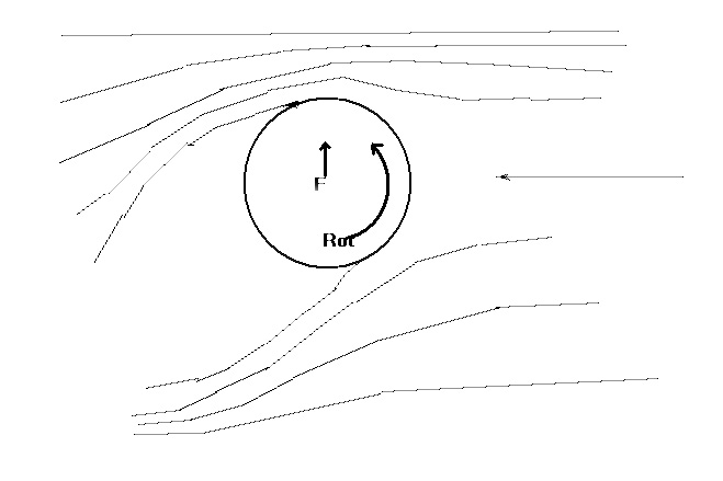
flux causes a force in the opposite direction(upwards in the case
shown in figure 1).
& nbsp; ; Figure 1. (Flow from right to left)
This phenomenon is influenced by the conditions in the thin layer next
to the body, known as the boundary layer, and there may
arise certain anomalies in the force if the spin of the body introduces
anomalies in the layer, such as making the flow turbulent on
one side and not the other. One such is the reverse Magnus effect which
may occur for smooth spheres. Rough balls such as cricket
balls, baseballs, golf balls and tennis balls, do not show this
anomalous
effect.
The dimple pattern on a golf ball helps generate lift by creating separation, but calculating what pattern is optimal is solvable only numerically but it would require huge computer resources. In general, I suspect that golf ball manufacturers come up with their dimpling designed based on experience and a sense of art. For example, MaxFli golf balls have an icosahedral pattern. There are 12 bigger dimples on the surface that represent the 12 corners of a 20 sided icosahedron.
Aerodynamic lift on an object is generated by the difference in pressure between the upper surface and the lower surface on an object in flight. If the air moving over the top of the ball moves faster than air going under the ball then the air above has a lower pressure than the air below the ball. This net pressure difference generates a force in the direction from higher pressure to lower pressure. This is often referred to as the Bernouilli effect.
From the perspective of fluid mechanics lift is created by circulation and circulation occurs when asymetric flow exists around an object. A body travelling through a fluid (like air) will push the fluid out of the way creating a wake like a boat going along the water.
Pressure multipled by area gives a force and the direction of that force is determined by normal vector of the area upon which the pressure is applied. For example, in a helium balloon the helium inside pushes outward while the air outside pushes inward. In the case of the golf ball we only care about the air pushing inward (toward the center of the ball).
Lift is one component of the aerodynamic force generated by the fluid (air) circulating about the object (in our case a golf ball) that opposes gravity.
Aerodynamic Force = vector summation of (-1 * pressure at the surface over d_area * d_area) * surface normal of d_area
where d_area is a small element of area of the surface, and surface normal of d_area is direction vector of the piece of area which is typcially taken to put away from the center of the three dimensional body and the -1 means that the pressure tends to push toward the inside of the body (in our case toward the center of the golf ball).
If you choose to have a coordinate system in which gravity is down (negative y-axis) and lift is up (positive y-axis) then
Lift = vector summation of (-1 * pressure at the surface over d_area * d_area) * (y component of surface normal of d_area)
and
Drag = vector summation of (-1 * pressure at the surface over d_area * d_area) * (x component of surface normal of d_area)
You could integrate these if you have an equation for pressure at every point on the surface of the golf ball.
In the case of non-turbulent flow the equation after summation or integration becomes:
Lift = fluid density * relative free stream speed * circulation
where fluid density is pretty much self explanatory, relative free stream speed is the relative speed of the fluid at a point where the object doesn't interfer with the flow, and circulation describes the asymmetric nature of the flow around the object. Equation 2 is referred to as the Kutta-Zhukhovski theorem and is used in airfoil calculations.
How to incorporate the dimple pattern into this formulation would be
tricky but could be done numerically in a simulation that calculated the
lift generated for various relative speeds of the ball and fluid and for
various spin rates of the ball.
I hope this helps your investigation of the dimple pattern.
Sincerely,
Tom "Spin Master" Cull
Text References:
Physics of Golf by Theodore P. Jorgensen AIP Press 1994
Fluid Mechanics by Pijush K. Kundu Academic Press, Inc. 1990
Try the links in the MadSci Library for more information on Physics.