MadSci Network: Physics
Query:

Re: image resolution limits

Area: Physics
Posted By: Adrian Popa, Staff Optical/Microwave Physics
Date: Wed May 21 15:00:24 1997
Area of science: Physics
ID: 863582649.Ph
Message:

Greetings:

You have asked a number of interesting interrelated questions. My answers are for typical human vision and typical optical components; however, there are special cases where my answers could be 50 % low or 50% high (+/- 50%). The text book that I am referring to is :

F. A. Jenkins and H. E. White; 
Fundamentals of Optics, McGraw-Hill, New York. 
Before you procede with this discussion you may want to review my answer to a question about how a magnifying glass works at the following MAD SCIENCE archives location:
Physics : RE: Why does an image turns upside down in a mag. glass? 
      Adrian Popa, Staff Optical/Microwave Physics, Wed Nov 20 11:39:48 1996

FUNDAMENTAL LIMIT OF OPTICAL RESOLUTION

The fundamental limit of optical resolution is determined by the wavelength of light that is used to illuminate the object. We cannot see objects or detail that is smaller than a light wavelength. Human vision spans from 720 nanometers (2.83 microinches) in the red wavelengths of light to 400 nanometers (1.57 microinches) in the blue violet wavelengths. Scientists typically use 560 nanometers (2.2 microinches) as an average value for white light containg all colors of the rainbow. (NOTE: a microinch = one millionth of an inch, a nanometer = one billionth of a meter).

We measure the resolution of an optical system, including human eyes, by the angular difference between two points of light that we can just resolve. At angles less than the resolution angle the points of light appear to be one bigger or brighter point. Scientists call these points of light POINT SOURCES and they can be double stars many millions of miles away or man made point sources in the laboratory. A number of double stars with different angular separation have been cataloged and amateur astronomers often use them to measure the resolution of their telescopes. An excellent point source of light which can be easily moved around the laboratory is light emitted from the end of an optical fiber. Special optical fibers called SINGLE MODE FIBERS have light guiding glass cores that are only one light wavelength in diameter making them excellent point sources of light at the fundamental limit of resolution.

HUMAN EYE RESOLUTION

As a small object is moved closer to a human eye it appears larger with more detail because it is filling more of the light sensors in the eyes retina. The human eye has maximum resolution when an object is viewed as close to the eye as possible before it goes out of focus. This point is called the NEAR POINT or the POINT OF MOST DISTINCT VISION. This point is about 25 centimeters (10inches) from the typical unaided human eye and the angular resolution of the eye at this point is about 1/60 degree (.0167 degree). This is equivalent to being able to resolve two fine human hairs spaced one hair width apart when placed at the point of most distinct vision . NOTE: a fine human hair is about 73 micrometers (29 microinches) in diameter. A fine hair is also about 130 wavelengths of light in diameter, so human vision at it's best has an angular resolution 130 times less than the fundamental optical limit of resolution. This is why we use telescopes and microscopes to improve our ability to see more detail in objects located at longer and shorter distances from the eye's near point and also improve our ability to resolve images at the near point. Also, the best optical instruments place their images at the eye's near point so that we can observe the greatest detail in these telescopic or microscopic images which are usually used to improve our eye's resolution through the process of magnification. There is a beautifully illustrated web book on human visual perception located at:

http://www.yorku.ca/research/vision/eye/

LIMITS OF RESOLUTION FOR OPTICAL LENSES AND MIRRORS

Microscopes and telescopes use combinations of optical elements (e.g. lenses, mirrors, prisms etc.) to aid human vision. However, no matter how complex the optical system is, the resolution of the instrument is set by the first lens or mirror in the system which gathers light to view the object. These optical elements are called the OBJECTIVE LENS or the PRIMARY MIRROR. The real image formed by the objective lens or the primary mirror is called the PRIMARY FOCUS. In the most basic instruments the image at the prime focus can be viewed by the observer with a magnifying lens called the EYEPIECE. Usually a number of transfer lenses and mirrors might also be used in the instrument.

An object and it's image can be considered to be composed of a large number of points of light which more recently have been called PIXELS (picture elements). This image formed at the primary focus by the objective determines the number of pixels in the image. The pixels can be magnifyed for viewing but the total number of pixels cannot be increased by magnification. This is similar to a television picture which is composed of 525 horizontal lines and about 250 vertical lines (525 x 250 = 131,250 pixels). The large screen television projections used in sports stadiums have about the same number of pixels as you home TV set (i.e the same resolution) only they are larger for more distant viewing.

The optical elements discussed above determine the following key parameters of the optical instrument:

  1. IMAGE RESOLUTION = (FOCAL LENGTH divided by DIAMETER) times WAVELENGTH (use dimensions of the objective lens or primary mirror)
  2. ANGULAR RESOLUTION = WAVELENGTH divided by DIAMETER (use dimensions of the objective lens or primary mirror)
  3. MAGNIFICATION = OBJECTIVE (or mirror) FOCAL LENGTH divided by EYEPIECE FOCAL LENGTH
  4. FIELD OF VIEW = OBJECTIVE (or mirror) DIAMETER divided by OBJECTIVE (or mirror) FOCAL LENGTH
In photography terms, the ratio F/D is called the F number (F#) of the camera lens. A small F# gathers more light, has a wider field of view, has a smaller depth of field and they also cost more.

The equations shown above illustrate that short focal length objectives and short focal length primary mirrors and larger diameter objectives give greater angular resolution, wider fields of view, less depth of focus; however, the greater curvatures required for short focal length optics give more distortion and are more expensive to manufacture.

Long focal length objectives have less curvature, give greater magnification, have greater depth of focus, have less distortion and are less costly to manufacture.

Larger diameter objectives or mirrors gather more light for night vision or dim distant objects in space, give greater angular resolution, have less depth of focus and cost more to manufacture.

Therefore all of these parameters must be optimized together for the specific application that the optical instrument will be used for and for an affordable cost. I will not discuss depth of focus, image distortion or chromatic (color) aberration here, but these are also major issues in optical instrument design.

DIFFRACTION

Diffraction is a consequence of the wave nature of light and plays a primary role in the design of optical elements. When waves pass an edge of a obstacle or pass through an aperture, they always spread out to some extent into the region which is not directly exposed to the on coming waves (e.g. in the shadow region). This apparent bending of light is called DIFFRACTION. In order to explain this bending of light, Huygens nearly three centuries ago proposed that each point on a wave front may be regarded as a new spherical source of waves. Huygens' principle can also be demonstrated with water waves.

HUYGENS' PRINCIPLE

Picture a calm harbor with a narrow inlet in a long straight break water facing the sea waves. When a long straight wave front from the sea hits the breakwater it is reflected back to sea, except for the part that passes through the opening into the harbor. As the wave enters the harbor drops of water on the crest of the center of the wave experience water at equal height to the left and right and the wave proceeds straight ahead. However, drops of water on the wave crest next to the left edge of the opening have no support on the left side when they enter the harbor and they start to run down hill both sideways and forward. The same thing happens to waves on the right edge only they run down hill to the right and forward. Eventually the sideways running of the waves also reaches drops in the center crest of the wave. These tilted waves continue to spread until a large semicircular wave front is formed that travels through the rest of the harbor. At a distance inside the harbor far from the breakwater, the inlet appears to be a point source for a perfect semicircular wave front that finally reaches the beach.

This water anology is similar to optical diffraction, light appears to bend around the edges of objects and propagates into the shadow region, only now the waves take on a spherical shape in three dimensions rather than a planar wave on the water surface. Diffraction also occurs during the converging of focused light waves, spreading some light waves into the shadowed region and smearing the resolution of images at the focal point to values greater than the one wavelength fundamental limit. This diffraction pattern in the focal region consists of a bright central disk, known as AIRY'S DISK, surrounded by a number of fainter rings.

http://marie.mit.edu/~bruen/airy.html

Neither the disk or the rings are sharply limited but shade gradually off at the edges, being seperated by circles of zero intensity.

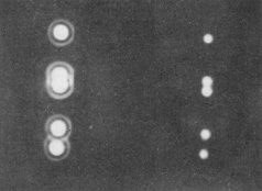
FIGURE Airy's disks for two different diameters of apertures. The aperture used for the images on the right side are about double the diameter of the aperture used to form the images on the left side. This demonstrates that the larger apertures on the right give smaller, higher resolution images.

The top set of images are of single point souces.
The middle images show two point sources just resolved.
The bottom images show two point sources completely resolved
A large number of tutorials on optics can be found on the Newport Corporations web pages at:

o http://www.newport.com/Optics/175050/1033/catalog.aspx

Also try: http://www.mellesgriot.com/products/optics/opticaltutorial.asp
http://www.hypermaths.org/quadibloc/science/opt0501.htm

APERTURE BLOCKAGE

Most telescopes have some form of aperture blockage to mount subreflectors and viewing cages. The 5 meter (200 inch) diameter Hale telescope on Mt. Palomar California has about a 1.5 meter hole in the center of it's 14.5 ton primary mirror. The primary focus is located 16.5 meters (55 ft.) in front of the primary mirror and an observers cage is sometimes placed at the prime focus causing more aperture blockage. This makes F/D in equation 1 equal to 3.3 giving the Hale telescope a theoretical resolution limit of 3.3 wavelengths. However, the aperture blockage degrades the limit of resolution of the mirror by about 20 %. In reality atmospheric turbulence blurs the image resolution of earth based telescopes much more than any aperture blockage.

Surprisingly, atmosphereic bluring causes a one meter diameter objective to provide the highest astronomical resolution possible when located on the earth's surface! The larger mirrors, such as the 5 meter Hale Telescope simply gather more light to view dim, distant objects at the edge of the universe, but the larger size does not improve resolution over a one meter diameter mirror. The new Keck telescopes are using active computer controlled, moveable, seqmented, primary mirrors to remove atmospheric bluring. This new technique, which is revolutioning astronomy, is discussed on the following Web pages where you can tour the great telescopes of the world. Here you will find that human observers are no longer used, being replaced by more sensitive electronic cameras.

http://astro.caltech.edu/
http://tarkus.pha.jhu.edu/~rbrunner/bookmarks/scienceHotList.html

Details of the Hubble Space Telescope, which does not have the atmosphere to limit it's resolution, can be found at:

http://www.stsci.edu/

In the technical description you'll find the Hubble's primary mirror to be 2.4 meters (94.5 inches) in diameter and the focal length to be 24 meters (79 ft.). Using equation 1 we get a limit of resolution = 10 wavelengths. The measured angular resolution published on the web pages is very close to the theoretical limit given by equation 2. This resolution is far better than old style earth bound telescopes.

Regards and good viewing, your Mad Scientist,
Adrian Popa
___


Current Queue | Current Queue for Physics | Physics archives

Try the links in the MadSci Library for more information on Physics.


MadSci Home | Information | Search | Random Knowledge Generator | MadSci Archives | Mad Library | MAD Labs | MAD FAQs | Ask a ? | Join Us! | Help Support MadSci


MadSci Network
© 1997, Washington University Medical School
webadmin@www.madsci.org